In short: the section properties tool in your CAD package will give you the area, the centroid and the second moments of area. What it will not give you is the torsion constant It, the warping constant Iw, the shear centre or the plastic section moduli Wpl — precisely the quantities you need for torsion, lateral-torsional buckling and a check to EN 1993. The MakeWise section properties calculator works them out straight from a DXF drawing. The biggest difference is in It: for open sections, the polar second moment of area from CAD overestimates it by up to three orders of magnitude.
For rolled sections you reach for the tables. For an aluminium extrusion, a bent sheet or a welded section the tables are no help and you are left with CAD. CAD answers the bending question quickly, but for torsion and stability it leaves you with no number at all — or worse, with a number that looks right and is not. Let us go through exactly what the calculator computes, what CAD cannot do, and why the torsion constant is the most important of the lot.
What the section properties calculator computes
The input is a DXF drawing of the cross-section: one profile per file, dimensions in mm, a closed outline (for hollow and thin-walled sections both the outer and the inner contour). The geometric quantities are obtained by integration over the area of the section; the torsion quantities — It, Iw and the shear centre — by solving the torsion-with-warping problem using finite elements. Results are in cm, cm², cm³, cm⁴ and cm⁶.
| Quantity | Symbol | What you need it for | Ordinary CAD |
|---|---|---|---|
| Area | A | axial force, mass | ✅ |
| Centroid | yc, zc | position of axes, eccentricities | ✅ |
| Second moments of area about the centroidal axes | Iy, Iz | bending, deflection | ✅ |
| Product moment of area | Iyz | reveals biaxial bending | ✅ |
| Principal moments and angle of the principal axes | I₁, I₂, α | bending of asymmetric sections | ✅ |
| Radii of gyration | iy, iz | slenderness, buckling | ✅ |
| Polar second moment of area | Ip | torsion of circles and tubes only | ✅ |
| Elastic section moduli | Wel,y, Wel,z | bending stress | usually not directly |
| St Venant torsion constant | It | torsion, lateral-torsional buckling, buckling | ❌ |
| Warping constant | Iw | non-uniform torsion, lateral-torsional buckling | ❌ |
| Shear centre | ys, zs | where the load acts without twisting | ❌ |
| Plastic section moduli | Wpl,y, Wpl,z | class 1 and 2 checks (EN 1993) | ❌ |
The last column applies to the section properties tool inside a CAD package. Simulation add-ins are a different story: SOLIDWORKS Simulation works out the torsion constant and the position of the shear centre itself for beam elements and can display them. You do not, however, get them as a section output you can drop into a report, and not even there will you get the warping constant or the plastic section moduli. Inventor gives you neither the torsion constant nor the warping constant directly at all — Autodesk points you to Inventor Nastran, with limitations.
If the product moment of area is non-zero, the calculator flags biaxial bending and shows the principal axes. It also warns about sharp corners in the DXF, which affect the torsion results locally.
The top half of the table is geometry, which CAD handles. The bottom half requires you to solve how the section warps under torsion, and that is something CAD does not do. This is exactly where the calculator delivers what you would otherwise only get from specialist structural software or a hand calculation.
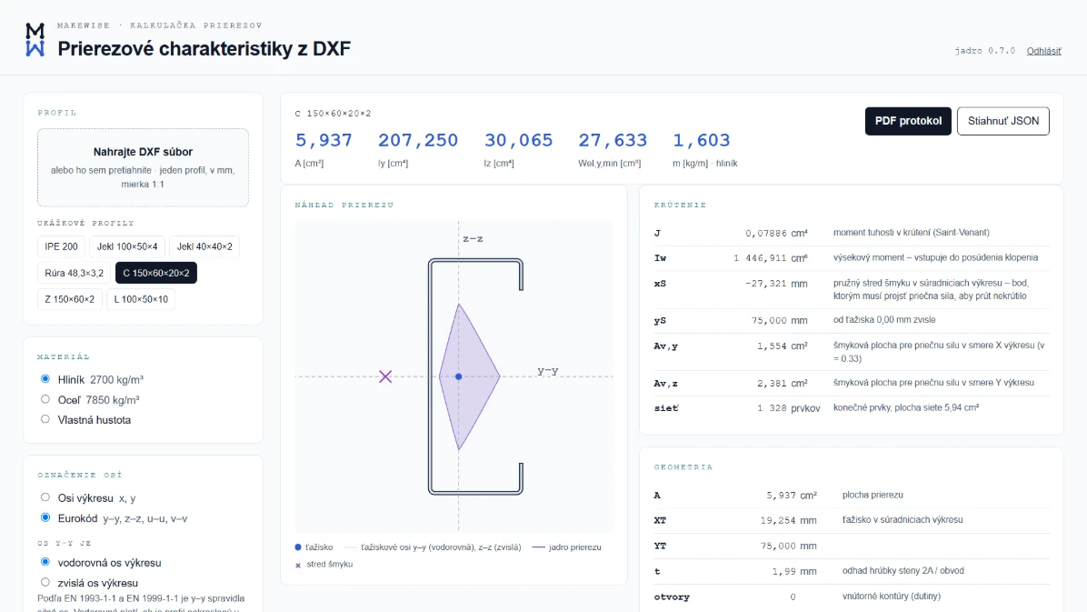
Output for an aluminium C section 150 × 60 × 20 × 2, with torsion switched on and Eurocode axis labelling. The cross in the preview is the shear centre — it lies outside the section. The worked example below uses this very section, so the numbers can be compared one to one.
Torsion is optional, because it is the only part of the calculation that needs finite elements. Switch it on and you also get It (the calculator labels it J), Iw, the position of the shear centre and the shear areas Av. The calculator also draws the core of the section (the kern), and the output can be downloaded as a PDF report or as JSON — ready to file with the calculation or to process further.
Sample output: C section 150 × 60 × 20 × 2 mm
The same section as in the image above: a channel with stiffeners, 150 mm deep, flanges 60 mm wide, stiffeners 20 mm, wall thickness 2 mm. The y axis is the strong axis (horizontal, parallel to the flanges).
| Quantity | Value |
|---|---|
| A | 5.94 cm² |
| Centroid from the outer face of the web | 19.25 mm |
| Iy / Iz | 207.25 / 30.07 cm⁴ |
| Iyz | 0 (symmetric about the horizontal axis) |
| iy / iz | 5.91 / 2.25 cm |
| Wel,y / Wel,z,min | 27.63 / 7.38 cm³ |
| Wpl,y / Wpl,z | 32.26 / 10.83 cm³ |
| Ip | 237.3 cm⁴ |
| It | 0.0789 cm⁴ |
| Iw | 1,447 cm⁶ |
| Shear centre | 27.3 mm behind the outer face of the web, outside the section |
Two numbers are worth pausing on. The shear centre lies outside the material, on the opposite side of the web from the centroid, 46.6 mm away from it. A load acting at the centroid therefore not only bends the section, it twists it — and for this profile the lever arm is almost five centimetres. And the torsional stiffness It is three thousand times smaller than the polar second moment of area that CAD would show you.
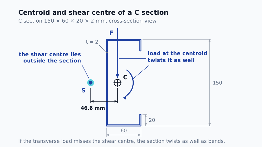
A load taken through the centroid twists the section as well, because the shear centre is somewhere else — for channel sections, outside the material altogether.
Why It is the most important quantity CAD will not give you
The polar second moment of area is not the torsion constant
The polar second moment of area Ip is a purely geometric integral:
The St Venant torsion constant It, also called the torsion constant or simply J in the English literature, determines the torque T needed to rotate the section through unit angle per unit length:
Both quantities have the same units, and that is the trap. The relation It = Ip holds only when the section stays plane under torsion, and that means a circle and a circular tube and nothing else. Every other section warps: its points displace along the axis of the member and the section offers less resistance to torsion. Hence It ≤ Ip, always.
How big is the difference
Values computed with the calculator and verified against analytical formulae. Dimensions in mm, sharp corners.
| Section | Ip [cm⁴] | It [cm⁴] | Ip / It |
|---|---|---|---|
| Circular tube Ø60 × 3 | 43.7 | 43.7 | 1.0 |
| Square 100 × 100 | 1,667 | 1,406 | 1.2 |
| RHS 150 × 50 × 3 | 365 | 150 | 2.4 |
| Flat bar 100 × 10 | 84.2 | 3.12 | 27 |
| Tube Ø60 × 3 with a 1 mm longitudinal slit | 43.5 | 0.16 | 274 |
| U section 150 × 50 × 3 | 253 | 0.22 | 1,150 |
| C section 150 × 60 × 20 × 2 | 237 | 0.0789 | 3,010 |
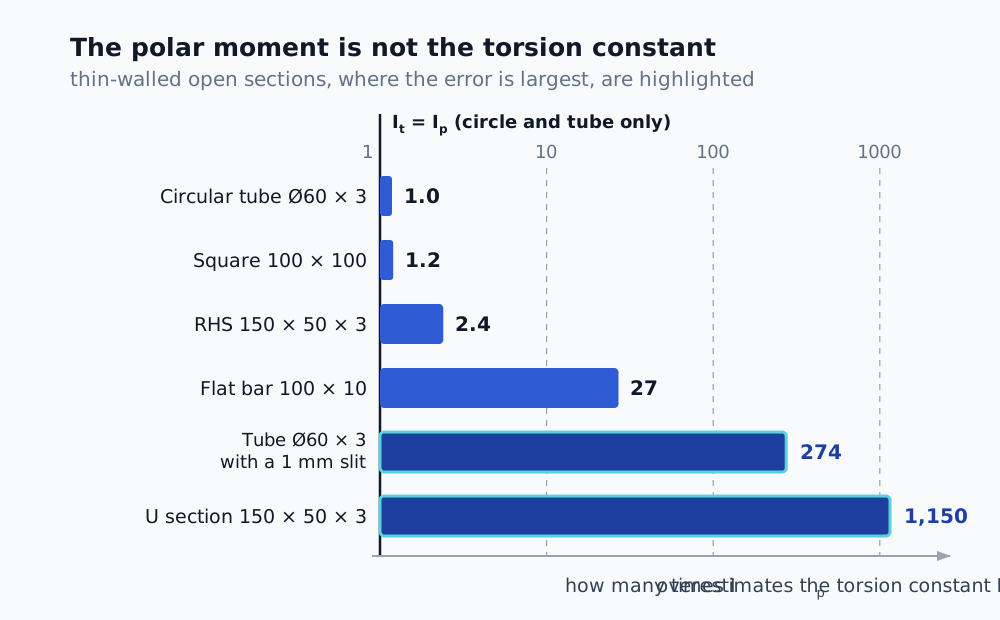
For closed sections the polar second moment of area is a usable estimate. For thin-walled open sections it overestimates the torsion constant by two to three orders of magnitude.
The slit tube: a slit one millimetre wide barely changes the area or Ip, but it reduces the torsion constant by a factor of more than 270. A closed section carries torsion by shear flow around the perimeter; an open one only within the wall thickness.
U section versus RHS: at the same outside dimensions of 150 × 50 × 3 mm, the RHS is roughly 680 times stiffer in torsion. The section from the example above, C 150 × 60 × 20 × 2, is worse still: a closed RHS of the same depth, width and thickness has It ≈ 143 cm⁴, so it is about 1,800 times stiffer. The turned-in stiffeners at the flange tips help the section considerably in bending and in stability — in torsion they help it almost not at all, because the profile remains open.
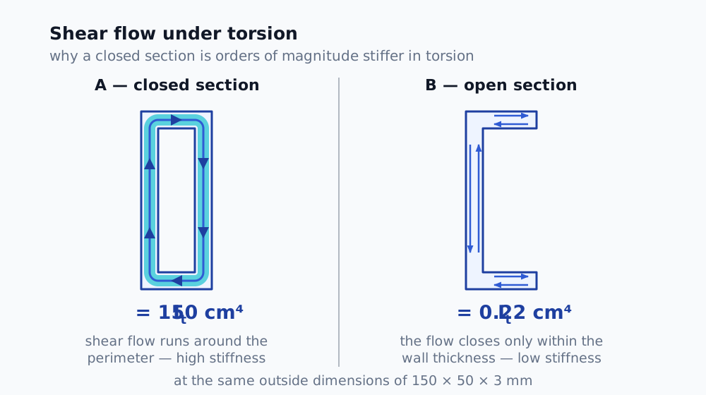
The whole difference lies in where the shear flow closes. A closed perimeter carries torsion on a lever arm across the full section, an open one only across the wall thickness.
Where the mistake happens in practice
- Beam model. For a custom section the software asks for the torsion constant, often labelled J, and the same letter is used for the polar second moment of area. It is all too easy for the CAD value to end up in that box, and the model then comes out orders of magnitude stiffer in torsion than the real structure.
- Torsion check. The shear stress from uniform torsion of an open section is τ = T · t / It. With Ip instead of It it comes out orders of magnitude lower.
- Stability. It enters the critical moment for lateral-torsional buckling and for flexural-torsional buckling. An overestimated It means a dangerously high resistance.
How to check It by hand
For a quick sanity check on the calculator's result:
Thin-walled open section (U, C, Z, L, bent sheet):
where bᵢ is the length of the wall mid-line and tᵢ its thickness. For C 150 × 60 × 20 × 2 the mid-line is 148 + 2 · 58 + 2 · 19 = 302 mm long, so It ≈ 302 · 2³ / 3 ≈ 0.081 cm⁴. The calculator gives 0.0789 cm⁴ — two per cent less, because the mid-line idealisation counts the material in the corners twice.
Thin-walled closed section (RHS, tube, box), Bredt's formula:
where Aₘ is the area enclosed by the wall mid-line. For an RHS 150 × 50 × 3 this gives It ≈ 148 cm⁴.
The calculator gives 150 cm⁴ for the same RHS. The 1.6% difference arises because Bredt's formula assumes a thin wall with shear flow uniform through the thickness, whereas the FE solution also captures the effect of the finite wall thickness and of the corners. For thin-walled sections the estimate is perfectly adequate in practice, but the difference grows as the wall gets thicker.
A general section (aluminium extrusion, combined welded section, fillets, cut-outs): here the analytical formulae run out, and the reliable route is an FE solution on the cross-section.
Other quantities CAD will not give you
Shear centre. The point the transverse load has to pass through if the section is to bend only. For symmetric sections such as an I beam or an RHS it coincides with the centroid; for U, C, Z and asymmetric sections it does not. For the C section in the example it is 46.6 mm from the centroid, outside the section.
Warping constant Iw. Where It describes free torsion, Iw expresses the resistance of the section when warping is restrained, for example at a fixed end. For open sections it often carries most of the torque, and it is essential when calculating the critical moment for lateral-torsional buckling. For C 150 × 60 × 20 × 2 it comes out as 1,447 cm⁶ — the stiffeners at the flange tips raise it substantially compared with a plain U section, which is precisely why stiffened channel sections are used where lateral-torsional buckling is a risk.
Plastic section moduli Wpl. Needed for checks on class 1 and 2 sections to EN 1993-1-1, where the plastic reserve of the section is used. For asymmetric sections the plastic neutral axis does not pass through the centroid, so Wpl cannot simply be derived from Wel.
Verification and the limits of the calculator
I verify the calculator's results independently of the computational core: with analytical formulae (as for It above), against the table values published by section manufacturers, and by comparison with an FE solution in another solver.
The calculator computes section properties, not a structural check. Responsibility for the use of the results in a calculation rests with the design engineer.
Got a non-standard profile?
If you need the section properties of a profile that has no tables — bent sheet, a welded section, an aluminium extrusion with chambers — get in touch. Attach the DXF of the cross-section: one profile per file, drawing in mm, a closed outline (both the outer and the inner contour).
If your problem goes beyond the section itself — the stiffness, fatigue or stability of a whole structure — have a look at what stress analysis and FEA services can cover.
Sources
- S. P. Timoshenko, J. N. Goodier: Theory of Elasticity, chapter on the torsion of prismatic bars
- W. C. Young, R. G. Budynas: Roark's Formulas for Stress and Strain, tables of torsion constants
- V. Z. Vlasov: Thin-Walled Elastic Beams (theory of thin-walled members, warping)
- EN 1993-1-1, cl. 6.2.7 Torsion
- R. van Leeuwen et al.: sectionproperties, an open-source library for cross-section analysis (Python)
About the author: Aleš Kurfürst, an analyst with 15 years of FEA experience (ANSYS, Altair) and a doctorate from TU Wien in computational modelling. At MakeWise he carries out strength, fatigue and stability analyses for engineering and manufacturing companies.
Frequently asked questions
- Which section properties does an ordinary CAD package calculate?
- CAD packages normally report the area, centroid, second moments of area Iy and Iz, the product moment of area, the principal moments and axes, the polar second moment of area and the radii of gyration. They do not normally calculate the torsion constant It, the warping constant Iw, the shear centre or the plastic section moduli Wpl. Simulation add-ins are a different story — SOLIDWORKS Simulation works out the torsion constant and the position of the shear centre itself for beam elements, but not even there do you get the warping constant or the plastic section moduli.
- Is the polar second moment of area the same thing as the torsion constant It?
- No. Ip = Iy + Iz equals It only for a solid circular section and a circular tube. For thin-walled open sections, It is a hundred to a thousand times smaller. For a C section 150 × 60 × 20 × 2 mm, Ip = 237 cm⁴ but It = 0.079 cm⁴ — three thousand times less.
- How do you calculate the section properties of a non-standard profile from a DXF?
- The geometric quantities (A, I, W) are integrals over the area of the section. The torsion constant It, the warping constant Iw and the shear centre require the torsion-with-warping problem to be solved, which is done by the finite element method on the cross-section.
- What is the shear centre and why does it matter?
- The shear centre is the point the transverse load has to pass through if the section is to bend only, without twisting. For channel (U) sections it lies outside the section — for a C 150 × 60 × 20 × 2 mm, almost 47 mm from the centroid.
- What is the warping constant Iw used for?
- Iw expresses the resistance of the section to warping under non-uniform torsion. It is essential when calculating the critical moment for lateral-torsional buckling and for the flexural-torsional buckling of open sections.