A non-linear static analysis stops. The solver reports a convergence failure, the time step is tumbling towards zero, penetration warnings are piling up. The analyst's reflex is: refine the mesh, add damping, cut the step. Sometimes that is right. Other times it is the most expensive mistake in the whole analysis — because a convergence failure is not a fault in the model, it is a message from the structure that it is losing stability. [1][2] Paper over it with artificial damping and you get a number you cannot defend.
I recently dealt with exactly such a case: a thin-walled transparent polymer shell in brittle acrylic, loaded locally through contact with a second body. The analysis kept dying on me. This article is about how to think through a problem like that, and how to work towards the physically correct answer.
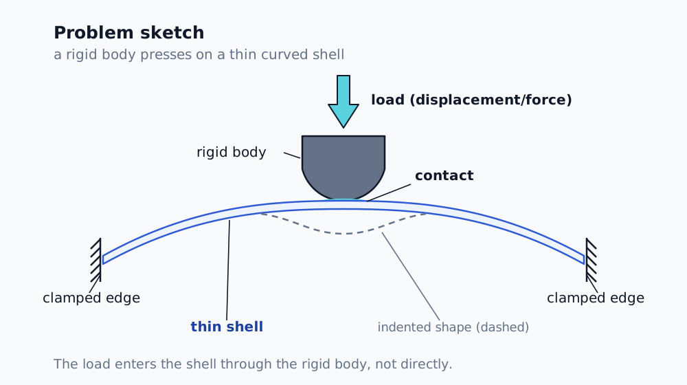
The problem: a thin shell loaded locally through contact with another body. The load enters the shell through that body, not directly.
The two faces of a loss of stability
The first and most important step is not technical at all. It is the question: which loss of stability am I actually looking at?
A global limit point (snap-through of the whole structure). The load reaches a maximum — the structure cannot carry any more and the force-displacement curve "flips over". This is a genuine exhaustion of capacity. If the solver dies here, it is a limit state of the entire structure. [2]
Local instability. An isolated region dimples or wrinkles (a patch of the thin shell has buckled inwards) while the global load is still rising. The static implicit scheme will not get through this jump — but that is not proof of collapse. It is a limit of the method, not a limit of the structure.
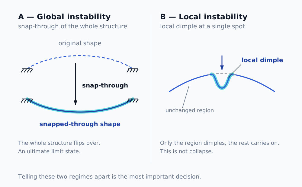
Global instability flips the whole structure over and is a limit state; a local one dimples only a region, while the rest carries on. Telling them apart is the key decision.
The difference is fundamental, because each calls for an entirely different response. Global limit = I have the capacity. Local instability = I need a method that can get past it, otherwise I am leaving the rest of the load on the table. (The theory of buckling, bifurcation and snap-through is covered in a separate article, Buckling and loss of stability.)
How I told them apart — reading the signals, not guessing
A convergence failure says nothing in itself. Diagnostics do.
Residuals node by node. I looked at the force residuals at individual nodes across the iterations. The residual turned out to be hyper-localised — a handful of nodes out of several tens of thousands carried the bulk of the L2 norm — and overwhelmingly in the normal direction. That ruled out two hypotheses at a stroke: global instability (which would give a residual spread over the whole surface) and stick-slip friction (which is tangential, not normal). [4]
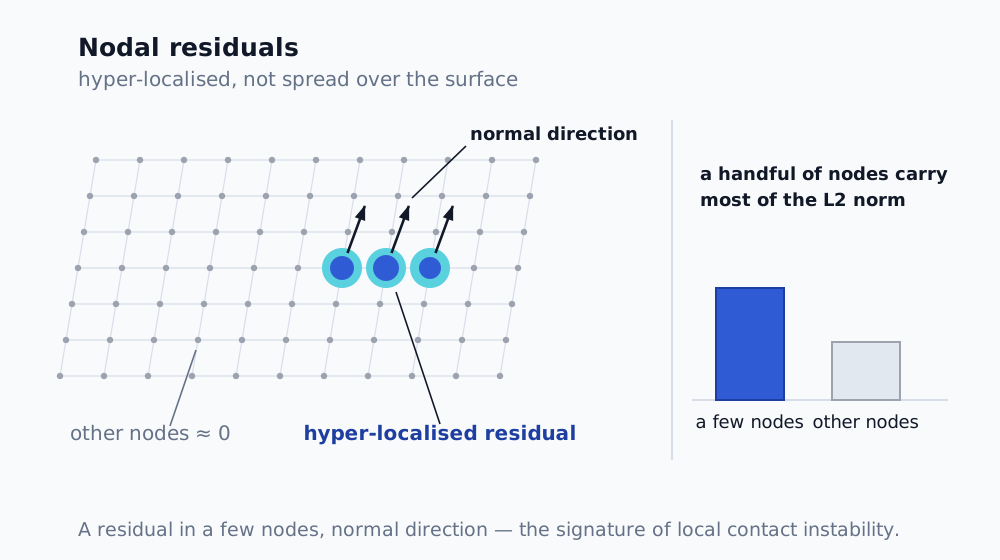
A residual concentrated into a handful of nodes and in the normal direction — the signature of a local contact instability, not of a global phenomenon nor of stick-slip friction.
The signature of chattering. When I compared the hot spot between iterations, it moved by one row of nodes. That is the typical signature of contact chattering, not of a progressing failure.
The contact jump. The number of active contact or target elements jumped from a steady value to almost double in a single iteration. A whole area engaged at once — under the pressing body the shell buckled inwards locally and wrapped around it, so a larger area came into contact. And the controlled degree of freedom (the prescribed displacement or load) does not control this internal degree of freedom, so the solver cannot bridge it statically.
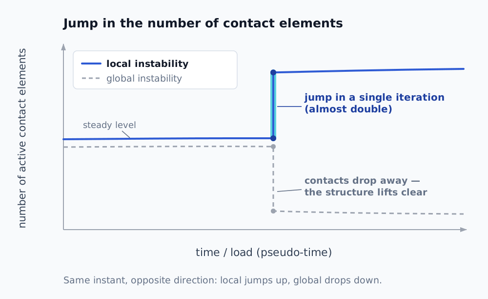
A sudden jump in the number of contact elements within a single increment is the signature of a local snap — a whole area engaged at once. With global instability the number of contacts collapses at that same instant instead: the structure flips away and loses contact.
The shape of the stiffness curve. The incremental stiffness dropped by tens of per cent and then settled — it was not heading to zero. A global limit point announces itself by the stiffness going to zero and the force reaching a maximum. [2] In my case the force rose monotonically, with no hint of a maximum. Conclusion: local instability, not a global limit.
Cross-check: two independent routes to the same number
Confidence in a non-linear result does not come from one run. It comes from two independent methods pointing at the same thing.
Eigenvalue buckling used as a diagnostic confirmed that the structure is prone to buckling in this regime — the load factors came out well below 1. And a Southwell estimate from an entirely different run landed at roughly half the design load, while the non-linear solver was dying at practically the same level. [6] When two independent approaches agree that "something real is happening around this level", a suspicion turns into a finding.
The physical picture: a thin shell in a tensile field
One more signal that is easily written off as an error while being pure physics: the minimum principal stress dropped almost to zero over large areas. A thin shell cannot carry compression — it wrinkles instead, and the compressive field collapses into a tensile one. [3] The deflection reached of the order of ten times the panel thickness; I am deep in geometric non-linearity, where membrane action dominates. Fail to recognise that state and you are computing on a model that does not apply.
The contact settings that unblocked the run
Before I could even reach the genuine instability, the model had to survive the numerical artefacts of contact. The changes that unblocked it:
| Setting | Originally | Corrected |
|---|---|---|
| Stabilization Damping Factor | 0 | 1.0 |
| Elastic Slip Tolerance | default | 1.0 mm absolute |
| Detection Method | — | On Gauss Point |
| Pinball region | default | 10 |
| Small Sliding | on | off |
The effect: the error messages and penetrations disappeared entirely, the substep that had been killing the run before went through in a few iterations, and instead of collapsing the time step grew.
Stabilisation — and why it was enough in this case
Non-linear stabilisation is a crutch — artificial energy dissipation that has to be justified on logical grounds and that can distort the result. More honest routes for snap-through do exist: the arc-length method, which solves the load and the displacement together and gets through the descending branch as well, or a quasi-static transient, in which the phenomenon runs dynamically. [1]
In the end I needed neither. It was enough to watch the increment of stabilisation energy against the strain energy () over the whole load path. As long as that ratio stays small, the artificial energy is negligible beside what is really working in the structure — and the stabilised solution can be taken as a regular equilibrium rather than an artefact of the damping. By reducing the damping to a level at which the incremental ratio stayed at a few per cent, I got a result that holds even without arc-length or a transient — and the critical load was independently confirmed on top of that by both eigenvalue buckling and Southwell.
Note: a low incremental ratio (a few per cent) is the standard acceptance criterion for stabilisation [5] and, together with the independent agreement of buckling and Southwell, gives confidence that the critical load is not an artefact of the damping. For the critical load itself, arc-length would have given practically the same thing — the difference would stay within the discretisation uncertainty. What it would mainly sharpen up is the post-critical branch beyond the limit point, which I do not need in this problem.
How I approach problems like this
- A convergence failure is a diagnostic, not merely an obstacle — I read the residuals before I reach for damping.
- I distinguish local instability from a global limit point: I watch whether the load path has a maximum and whether the stiffness is heading to zero.
- I build confidence in a non-linear result on independent confirmation (buckling, Southwell), not on a single run.
- Zero minimum principal stress in a thin shell is a tensile field, not an error.
- Stabilisation is acceptable if the increment of stabilisation energy stays small against the strain energy — and then I need neither arc-length nor a transient.
When an analysis refuses to converge, the first question I ask myself is whether the model is telling me something about the structure. The answer is often not more damping — it is better diagnostics.
Are you a design engineer or an analyst with a problem on your desk that you cannot crack? A non-linear model that will not converge, a contact that keeps falling over, or a result you do not believe — this is exactly the sort of thing I deal with. Write to me at ales@makewise.sk or through the contact form and we will look at it together.
Sources
- Crisfield, M. A. Non-Linear Finite Element Analysis of Solids and Structures, Wiley, 1991.
- Timoshenko, S. P., Gere, J. M. Theory of Elastic Stability, 2nd ed., McGraw-Hill, 1961.
- Timoshenko, S. P., Woinowsky-Krieger, S. Theory of Plates and Shells, 2nd ed., McGraw-Hill, 1959.
- Wriggers, P. Computational Contact Mechanics, 2nd ed., Springer, 2006.
- Ansys, Inc. Mechanical User's Guide / Theory Reference — non-linear stabilisation (the stabilisation versus strain energy criterion) and the NLDIAG contact diagnostics.
- Southwell, R. V. On the Analysis of Experimental Observations in Problems of Elastic Stability, Proc. Roy. Soc. London A, 135, 601–616 (1932). DOI 10.1098/rspa.1932.0055.
Frequently asked questions
- Does a non-linear analysis that fails to converge mean the structure has collapsed?
- Not necessarily. It means the static implicit scheme cannot get through that particular point. If the structure has reached a maximum load and the stiffness is heading to zero, that is a genuine exhaustion of capacity. If the force keeps rising and the stiffness settles after dropping, it is more likely a local instability — a limit of the method, not a limit of the structure.
- How do you tell local instability from global?
- By the signatures in the data. A local one has the force residual concentrated into a few nodes and in the normal direction, a sudden jump in the number of active contact elements within a single increment, and a stiffness that drops and then settles. A global one has the residual spread over the surface, a number of contacts that at the very same instant collapses instead, and a stiffness heading to zero together with a maximum on the force-displacement curve.
- When is numerical stabilisation acceptable?
- When the increment of stabilisation energy stays small against the increment of strain energy over the whole load path — of the order of a few per cent. The artificial dissipation is then negligible beside what is really working in the structure. The analysis simply running to completion is no proof on its own.
- Why does the minimum principal stress in a thin shell come out close to zero?
- Because a thin shell cannot carry compression — it wrinkles instead, and the compressive field collapses into a tensile one. This is not an analysis error but the physics of membrane action at large deformations.